
Page 4 - RDX-series
P. 4
Features:
Operation and failure LED indication Environmentally and ozone-friendly refrigerants
Dew point indicator with a colour scale R134a and R404a
Hot-gas bypass regulation for an adjustment of Efficient thermally insulated heat exchanger
refrigeration capacity Modern and reliable refrigerant compressors
Reliable drain valve and electronic timer to
control periodic operation
Functional block diagram refrigerated dryers RDX
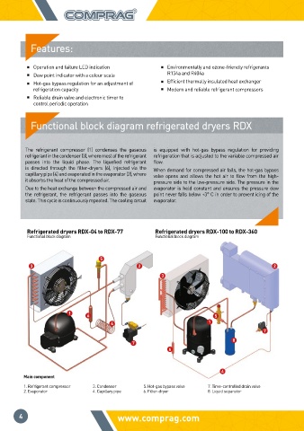
The refrigerant compressor (1) condenses the gaseous is equipped with hot-gas bypass regulation for providing
refrigerant in the condenser (3), where most of the refrigerant refrigeration that is adjusted to the variable compressed air
passes into the liquid phase. The liquefied refrigerant flow.
is directed through the filter-dryers (6), injected via the When demand for compressed air falls, the hot-gas bypass
capillary pipe (4) and evaporated in the evaporator (2), where valve opens and allows the hot air to flow from the high-
it absorbs the heat of the compressed air. pressure side to the low-pressure side. The pressure in the
Due to the heat exchange between the compressed air and evaporator is held constant and ensures the pressure dew
the refrigerant, the refrigerant passes into the gaseous point never falls below +3° C in order to prevent icing of the
state. This cycle is continuously repeated. The cooling circuit evaporator.
Refrigerated dryers RDX-04 to RDX-77 Refrigerated dryers RDX-100 to RDX-360
Functional block diagram Functional block diagram
5
3 2 2
3
1 6 5
4 1
7
8
7
6
4
Main component
1. Refrigerant compressor 3. Condenser 5. Hot-gas bypass valve 7. Time-controlled drain valve
2. Evaporator 4. Capillary pipe 6. Filter-dryer 8. Liquid separator
4 www.comprag.com COMPRESSED AIR PREPARATION REFRIGERATED DRYER RDX-series