
Page 10 - A-series
P. 10
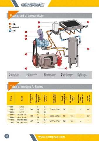
Flow chart of compressor


                                  7                                        8
           -OIL
           -OIL+AIR               6
           -AIR
                       4
                      3
                      1


                                                                           5

                       9


                       2                                10

         1. Screw air-end  3. Air intake valve  5. Separation vessel  7. Spin-On separator  9. Belt drive
         2. Electric motor  4. Air filter  6. Spin-On oil filter  8. Heat exchanger  10. Cooling fan


          Table of models A-Series


           Article  Model  Drive power   (kW)  Max. working   pressure  (bar)  Capacity*  (m³/min)  Rated voltage  (phase/V/Hz)  Sound  pressure level**  dB(A)  Air receiver   capacity  (liter)  Refrigerated   dryer,  RDX-Series  Screw  connection


       11100041   A1808          8    3,1
       11100042   A1810   18,5  10    2,5  3/380-420/50  70   -      -     3/4”
       11100043   A1813         13    2,2
       11100045  AR1808-500  18,5  8  3,1  3/380-420/50  70  500     -     3/4”
       11100046  AR1810-500     10    2,5
       11110023  ARD1808-500  18,5  8  3,1  3/380-420/50  70  500    x     1”
       11110024  ARD1810-500    10    2,5


      10                         www.comprag.com                                                              STATIONARY SCREW COMPRESSORS A-SERIES