
Page 22 - A-series
P. 22
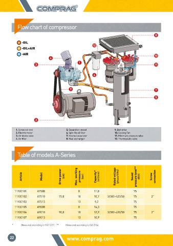
Flow chart of compressor

                                                                            8
            -OIL
                                              12
            -OIL+AIR
            -AIR                                                            10
                         4
                                       1
                  3                                                         11

                                              6


                                   9                                        7

                                                                            5


                  2

         1. Screw air-end        5. Separation vessel    9. Belt drive
         2. Electric motor       6. Spin-On oil filter   10. Cooling Fan
         3. Air intake valve     7. Internal separator   11. Minimum pressure valve
         4. Air filter           8. Heat exchanger       12. Thermostatic valve


          Table of models A-Series


            Article  Model     Drive power   (kW)  Max. working   pressure  (bar)  Capacity*  (m³/min)  Rated voltage  (phase/V/Hz)  Sound  pressure level**  dB(A)  Screw  connection


        11100101   А7508               8       11,8               75
        11100102   А7510      75,0     10      10,7  3/380-420/50  75     2”
        11100103   А7513               13      9,2                75
        11100105   А9008               8       14,3               75
        11100106   А9010      90,0     10      12,9  3/380-420/50  75     2”
        11100107   А9013               13      10,9               75

       *              Measured according to ISO 1217;   **            Measured according to ISO 3744

      22                         www.comprag.com                                                              STATIONARY SCREW COMPRESSORS A-SERIES